
- #MULTISIM 14.1 HOW TO USE AC CURRENT INPUT GENERATOR#
- #MULTISIM 14.1 HOW TO USE AC CURRENT INPUT SIMULATOR#
The Function Generator is a voltage source that supplies sinusoidal, triangular or square waves. Once you're done designing and testing, you can export your design t You have access to numerous virtual versions of bench top test equipment like an oscilloscope, function generator, spectrum analyzer, network analyzer, logic analyzer, etc. The component library is EXTENSIVE and easy to navigate. It's format and layout are simple and easy to use. Multisim is the most complete and robust circuit design and simulation suite available. Multisim guides use the convention of an arrow ( ) to indicate the start of procedural information For example,File/Open means choose the Open command from the File menu. Multisim guides use the convention Menu/Item to indicate menu commands.  When Multisim guides refer to a toolbar button, an image of the button appears in the left column. VEE stands for Voltage at Common Emitter that is the negative supply voltage Multiple Voltage Sources (VCC / VDD) in Multisim - NI VCC stands for Voltage at Common Collector that is the positive supply voltage. Select the voltage prob The VCC and VEE are the notations used for the voltages at various common voltage terminals. Here we are measuring the voltage across R1. Place this on the wire that you would like to measure with reference to. Locate a reference probe on the left hand side of the screen 4. Locate the voltage probe icon at the left hand side of the screen 2. To measure voltage in Multisim we use probes. The Value tab in this component's properties dialog box contains the following: Parameter. It functions the same as the single pole double throw switch, except that the same control voltage controls two independent switches. The Voltage Controlled DPDT is double-pole, double-throw switch. This prevents high frequency oscillation from occurring when the timing. Currently the carrier signal is set to 87.5% duty cycle so that a narrow pulse (the remaining 12.5%) will be applied to the TRIGGER input of the 555. For a +Vcc/-Vcc modulation signal the control voltage varies between Vcc/4 and 3Vcc/4. When the modulating signal is at 0 V, the control voltage is at one half the supply voltage (Vcc/2). The 10 kOhm modulation resistor attenuates the modulating signal by a factor of 4. By default, digital components are connected to VCC and GND or VSS and VDD, simply place the appropriate source symbol anywhere on the schematic to power up the IC As long as the net name exists anywhere on the schematic, the digital component is virtually connected. This value is also used by the measuring devices like the meters, scopes, bode plots etc. e what the output will look like, so if the chips VCC is +5V and GND, then the output would swing between +5 and GND. Connect all the components with proper wiring and also ensure that nodes are formed at the interconnection point
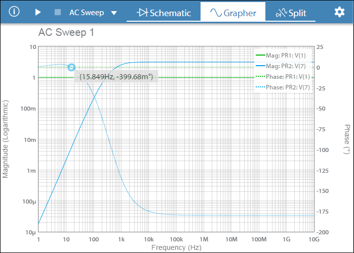
Double click on the AC power source, and change the voltage to 25mV and frequency to 1khz.
Multisim Live is a free, online circuit simulator that includes SPICE software, which lets you create, learn and share circuits and electronics online Place the Vcc on the multisim design window and double click on Vcc to change the value to 12V. What happens is that the original instance of VDD or VCC is copied instead and you have to rename and reset the Voltage level of this newly copied source to match the desired Vsettings. You can edit the refdes of the original VCC or VDD in Multisim, however this presents a problem if you would like to copy this newly created source multiple times in Multisim. At times it is required to have multiple voltage sources in Multisim (such as VCC1, VCC2). Place a configure the dual power supplies used for circuits based on bipolarjunction transistors (BJTs). Home What is VCC in Multisim Live NI Multisim: VCC and VEE power supplies - YouTub


 0 kommentar(er)
